U-Boot stuck on Allwinner H616 and axp313a
This is a short note to fix the stuck issue when working with axp313a.
TL;DR
The fix is here, you lazy ass.
Quick note
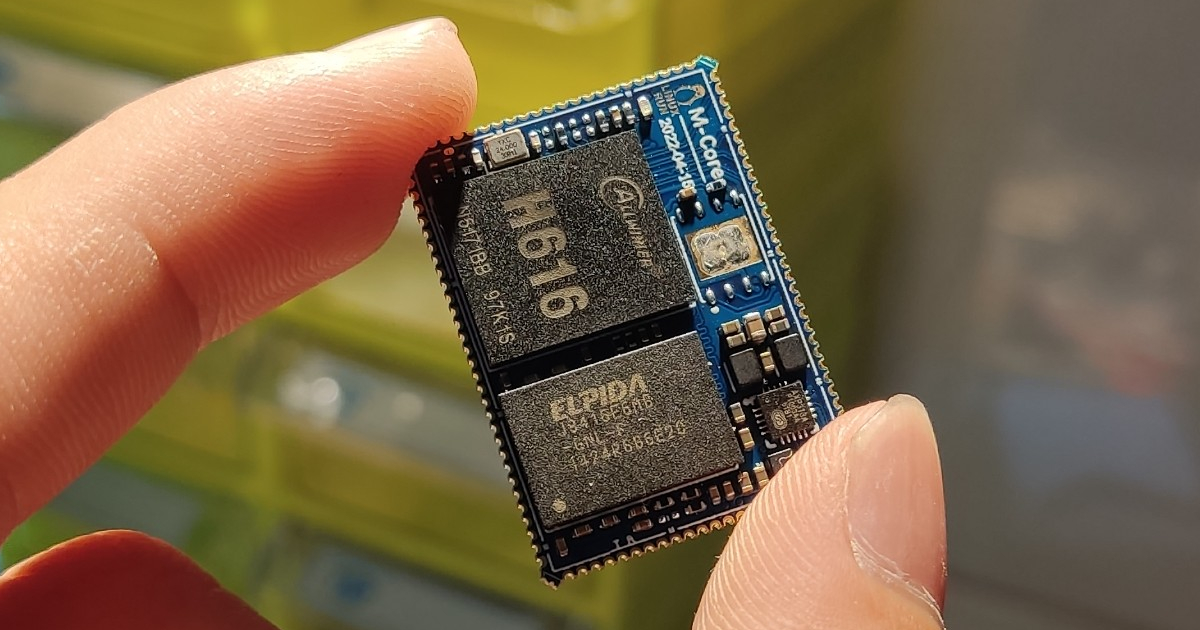
I have used Orange Pi Zero2 for another project previously. It uses an Armbian pre-built image. Recently, I have been working on a project using mcore-h616 which has a similar design to MQ-Quad. The image file produced by the Mango Pi website for MQ-Quad is working perfectly with mcore-h616. But I only want a simple Linux system rather than a big Debian full of bloat. I’m starting to build my own using Buildroot. My u-boot build likely won’t work.
My board has a 1 GiB RAM but it shows 128 MiB and sometimes changes to some random power-of-2 number. My first thought was DRAM config or PMIC in dts config was wrong.
It took me almost a week to try to change the config in uboot config and dts. I have searched all of Google, and DuckDuckGo,.. trying to read everything to config my dts for axp313. Nothing in the English article could help me =]].
Then today, I thought I would copy 1 MiB section of the MQ-Quad image to just get the job done and give up. But when it boot, the boot message has a weird line on the boot: pmic id is 0x4b`. I tried Googling the quote “pmic id is”. The last result (out of 11) got me to a Chinese website (Allwinner forum).
In this forum, the user evler has an article to build u-boot, kernel, and buildroot for MQ-Quad. I tried to change drivers/power/axp305.c to his instruction. It runs perfectly. After that, I did some small research to try to understand how it works.
My power tree
Before going to explain what happened, you need to know my power tree:
| PMIC | VDD-CPU | VDD-GPU | VDD-DRAM | |
|---|---|---|---|---|
| mcore-h616 | AXP313a | DCDC2 | DCDC1 | DCDC3 |
| OPiZ2 | AXP305 | DCDC-A(1) | DCDC-D(3) | DCDC-E(4) |
| Normal voltage (V) | 0.9 | 0.9 | 1.5 |
The solution
Edit file [u-boot]/drivers/power/axp305.c
1
2
3
4
5
6
7
8
9
10
11
12
13
14
15
16
17
18
19
20
21
22
23
24
25
26
27
28
29
30
31
32
33
34
35
36
37
38
39
40
41
42
43
44
45
46
47
48
49
50
51
52
53
54
55
56
57
58
59
60
61
62
63
64
65
66
67
// axp313 doesn't have dcdc4 so all call to this will return with 0
// This function will be called at board/sunxi/board.c:sunxi_board_init()
int axp_set_dcdc4(unsigned int mvolt)
{
	return 0;
}

#define AXP305_DCDC3_1200MV_OFFSET 71

// This function will *NOT* be called at board/sunxi/board.c:sunxi_board_init()
// if CONFIG_AXP305_POWER=y
// Instead dcdc4, we setup a new function to set dcdc3 voltage and call it
// at axp_init()
int axp_set_dcdc3(unsigned int mvolt)
{
	int ret;
	u8 cfg;

	if (mvolt >= 1220)
	{
		cfg = AXP305_DCDC3_1200MV_OFFSET +
			axp305_mvolt_to_cfg(mvolt, 1220, 1840, 20);
	}
	else
		cfg = axp305_mvolt_to_cfg(mvolt, 500, 1200, 10);

	if (mvolt == 0)
		return pmic_bus_clrbits(AXP305_OUTPUT_CTRL1,
					AXP305_OUTPUT_CTRL1_DCDCD_EN);

	ret = pmic_bus_write(AXP305_DCDCD_VOLTAGE, cfg);
	if (ret)
		return ret;

	return pmic_bus_setbits(AXP305_OUTPUT_CTRL1,
				0x1f);
}


// So 0x4b is chip version id
// Change 0x40 to 0x4b
// and set dcdc3 at 1.5v
int axp_init(void)
{
	u8 axp_chip_id;
	int ret;

	ret = pmic_bus_init();
	if (ret)
		return ret;

	ret = pmic_bus_read(AXP305_CHIP_VERSION, &axp_chip_id);
	if (ret)
		return ret;

	// if ((axp_chip_id & AXP305_CHIP_VERSION_MASK) != 0x40)
	// 	return -ENODEV;

	if ((axp_chip_id & AXP305_CHIP_VERSION_MASK) != 0x4b)
		return -ENODEV;

	printf("pmic id is 0x%x\n",axp_chip_id);

	axp_set_dcdc3(1350); // Set Vdd-ram = 1350mV, mcore-h616 has a DDR3L ram

	return ret;
}
Save, rebuild and you’re good to go.
Explain
After the call to axp_init(), board/sunxi/board.c:sunxi_board_init() won’t set up any other output voltage that AXP313a has. dcdc1, dcdc2, aldo1, and dldo1 should be set up somehow, by default voltage (I guess). Because the axp313a datasheet is written in Chinese and not well documented (I think), I found nothing about default voltage. I even can’t figure out what set XXH default register in their datasheet. Where the fck is your default values, Allwinner?
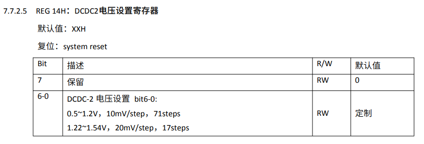 DCDC2 Voltage register of AXP313a from here (v0.1)
There is another version of the axp313a datasheet (v1.0) but not really improved. AXP313a [may] be compatible with AXP305 so AXP305 datasheet might help.
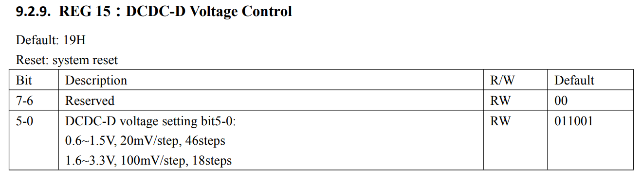 DCDC4 (DCDC-D) Voltage register of AXP305
With the image above, we can easily calculate the default output of DCDC4 of AXP305, is 1.1 V. On the OPiZ2 DCDC4 is wired to VDD-DRAM which needs at least 1.35 V. That explains why the old code has the function axp_set_dcdc4(). It sets the output of DCDC4 to correspond to CONFIG_AXP_DCDC4_VOLT (u-boot). The new code axp_set_dcdc3() does that too.
But where is the code to set up DCDC1 DCDC3 ? Look at the datasheet, and do the math. The default value of each is 0.9 V, a normal value for H616’s CPU and GPU. And trust me, I believe AXP313a does so <3.
You only need that, to survive through u-boot. When the kernel is loaded, it will take care of your PMIC.
BTW, finding these Chinese’s-product datasheets is like a pain in the ass!